Frequency meter
From ShawnReevesWiki

Specifications
- Connect 1 Hall effect switch to watch a magnet passing once per cycle.
- Include a display with at least 4 characters.
- Include a power switch to save the battery, and/or a reset switch.
- Use a breadboard so it can be built by students, or modified.
- Allow timing of periods up to at least 10s, accurate to 0.01s.
Circuit

Components
- Breadboard (~$5)
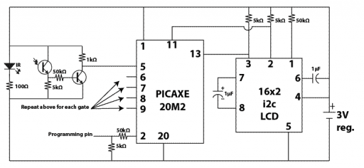
- Micro-controller. I use a PICAXE 20M2 (software timing) or a 20X2 (dedicated hardware timing for better accuracy); both have plenty of inputs and outputs for multiple gates and any type of display. ($4-$6)
- Resonator circuit if necessary. Not available for PICAXE 20M2. (~$1)
- Display
- LCD Display, serial capable. I use Newhaven's NHD-C0216CiZ-FSW-FBW-3V3 LCD with I2C ($10)
- Two 1µF capacitors to aid voltage booster circuit.
- Two 5kΩ resistors to pull up serial clock and data lines while idle.
- One 50kΩ resistor to pull up reset.
- Alternatively, a TTL-to-USB or TTL-to-serial circuit for sharing data with computer ($18)
- LCD Display, serial capable. I use Newhaven's NHD-C0216CiZ-FSW-FBW-3V3 LCD with I2C ($10)
- Hook-up wires ($2)
- Power supply
- 9V or a quartet of AAA with a 5V voltage regulator, capacitor(s), resistor(s), or
- 120V AC to 5V DC adapter, or
- Three alkaline AAA or AA batteries.
Program
For an explicit example, see Frequency meter with a PICAXE 08M2.
- Initiate the display
- Set an interrupt on the pin attached to the first gate. Will interrupt the program wherever execution is and go to Interrupt.
- Loop.
- Increment time counter.
- Go back to Loop.
- Interrupt
Datasheets
See also
See more discussion and other circuits at Circuits for teaching physics.