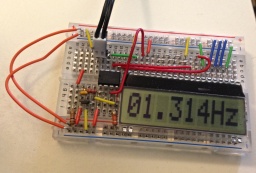
Frequency meter
Specifications

- Connect 1 Hall effect switch to watch a magnet passing once per cycle.
- Hall effect switch may be unipolar or omni-polar, but not bipolar. If unipolar, take care to place magnet correctly.
- Switching time needs to be shorter than inverse of desired highest frequency.
- Include a display with at least 4 characters.
- Include a power switch to save the battery, and/or a reset switch.
- Use a breadboard so it can be built by students, or modified.
- Allow timing of periods up to at least 10s, accurate to 0.01s.
One difficult thing about frequency meters is that they operate by counting pulses over a given amount of time, which is only good for steady frequencies, or they count time between two pulses, which gives a period which must be a divisor in a calculation done by the micro-controller often with limited maths abilities. The fact that it is a divisor means that the precision will be inversely proportional to the frequency, in the absence of floating-point maths. The frequency will have a low limit due to the instruction-time of the micro-controller, and an upper-limit due to this divisor effect. It might be possible to add a switch to notify the micro-controller of the expected range.
Circuit

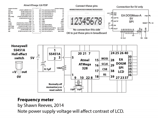
For a detailed, printable diagram, see File:Frequency-meter-Arduino-on-a-board.pdf. For a previous version using a much less precise PICAXE 08M2, see File:Frequency meter-PICAXE-08M2.pdf.
Components
See #Datasheets for specific tips.
- Breadboard (~$5)
- Hall effect switch, unipolar or omni-polar, with quick output rise and fall times.
- Micro-controller. I use an Atmel ATmega328. A previous version used a PICAXE 08M2. (both $3)
- Resonator circuit if necessary. The ATmega328 uses a 16MHz crystal and two ~20pf capacitors. (~$1)
- Display
- LCD Display, serial capable. I use Electronic Assembly's DOGM081 with SPI. ($10)
- Alternatively, a TTL-to-USB or TTL-to-serial circuit for sharing data with computer ($18)
- Hook-up wires ($2)
- Power supply. Our LCD is expecting 4.7V to 5.3V.

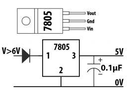
- 9V or a quartet of AAA with a 5V voltage regulator and capacitor(s), or
- 120V AC to 5V DC adapter—I find phone chargers at thrift stores for $1 each, or
- Three alkaline AAA or AA batteries, or
- Four NiMH rechargeable batteries, or
- Three NiMH rechargeable batteries with a 5V voltage booster.
Program
Program without a hardware timer
For an attempt on the PICAXE 08M2, see Frequency meter with a PICAXE 08M2.
- Initiate the display
- Set an interrupt on the pin attached to the switch. Will interrupt the program wherever execution is and go to Interrupt.
- Loop.
- Increment time counter.
- Display frequency.
- Go back to Loop.
- Interrupt
- Convert count to Hz.
- Reset counter.
Program with a hardware timer
For an working example, see Frequency meter on Arduino.
Keep interrupt service routines as short as possible by having them set the minimum amount of variables and instead do the calculations in the main loop.
- Initiate the display
- Set a timer interrupt. Will interrupt the program wherever execution is and go to associated interrupt routine.
- Set a falling or low interrupt on the pin attached to the switch. Will interrupt the program wherever execution is and go to associated interrupt routine.
- Loop:
- If there's a time recorded, note it and erase it.
- If also there's a previous time recorded, calculate frequency.
- If frequency is updated, display frequency.
- Go back to Loop.
- If there's a time recorded, note it and erase it.
- Switch-detecting interrupt routine:
- Record the time now.
- Timer-detecting interrupt routine:
- Increase the time variable.
Datasheets
- Atmel ATmega328P-PU
- 28-pin PDIP micro-controller. http://www.atmel.com/images/atmel-8271-8-bit-avr-microcontroller-atmega48a-48pa-88a-88pa-168a-168pa-328-328p_datasheet.pdf
- Electronic Assembly ED DOGM081-A
- 8-character LCD dot matrix display, with SPI serial control. http://www.lcd-module.com/eng/pdf/doma/dog-me.pdf
- Read various forums for discussions on using SPI between the micro-controller and this display. For example, one on how CSB must be used: http://forums.parallax.com/showthread.php/134847-EA-DOGM-162-Display
- Is the display too dark? The supplied voltage is too high, try to bring it down a bit. I tame a 6V supply with a single 1N914 diode for low power circuits like this.
- Diodes Incorporated Hall effect switch
- This switch has a long rise and fall time, so it is not good for greater than 8Hz; but it uses very little power.
- http://diodes.com/datasheets/AH180.pdf
- Honeywell SS451A omnipolar Hall-effect digital position sensor
- Works with supplies between 3.0 and 24V, taking 4.5mA at 5V. It switches on at about 85 Gauss and off at about 50 Gauss, in either direction, in less than 1.5µs.
- http://sensing.honeywell.com/index.php?ci_id=45443
- TT Electronics OH090 unipolar Hall-effect sensor
- The OH090 is their most sensitive device, and it switches on and off in less than a microsecond. It requires the magnet to be oriented correctly, since it turns on (voltage drops to zero) when its face is exposed to a field of about 90 Gauss only from the south pole.
- http://optekinc.com/datasheets/OH090-OHS3100.PDF
- PICAXE micro-controller system for education
- http://picaxe.com
See also
See more discussion and other circuits at Circuits for teaching physics. Bicycle speedometer is essentially the same circuit and program, only displaying a different unit, and possibly adding an interface to change the wheel-diameter.